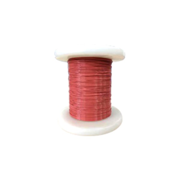
1. Directly solderable.
2. Suitable for high-speed winding with automatic winding machines.
3. Meet EU RoHS 2.0, HF halogen-free, and REACH SVHC environmental requirements.
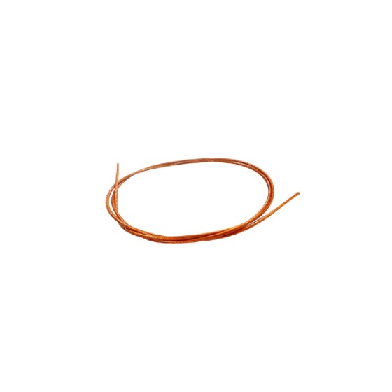
Product structure diagram

Product Parameters
| conductor |
Bare copper wire |
| Material |
PET, PA |
| Temperature tolerance grade |
Class B |
| Withstand voltage |
AC 6000V/60S no breakdown |
| Hierarchy |
three layers |
| Application scope |
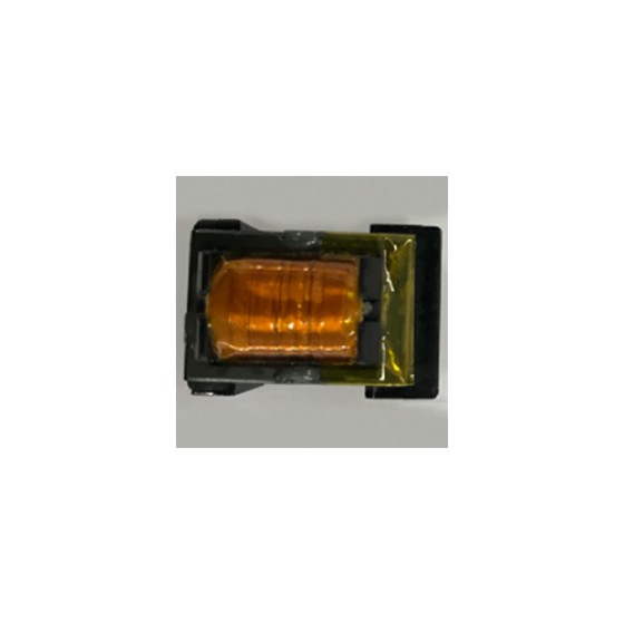
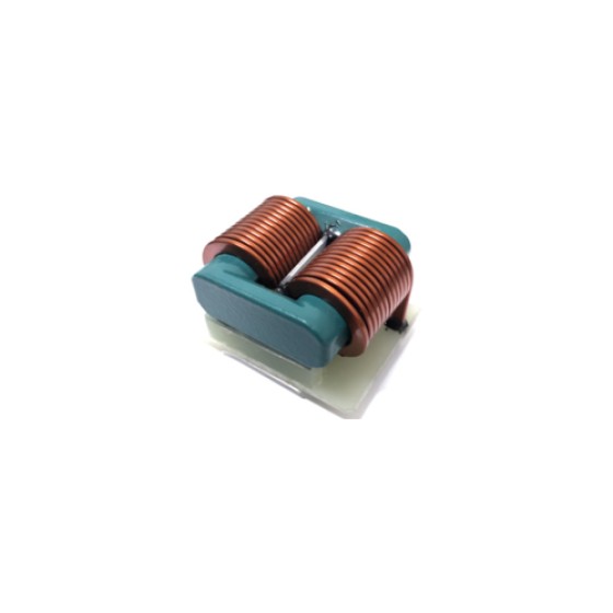
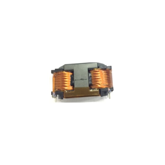
high-frequency transformer, power supply, inductor, charger, adapter, communication network, LED wire
High frequency transformer, power supply, inductance, charger, adapter, communication network, LED conductor |
| Pass safety regulations |
UL: UL2353, UL60950; VDE: IEC/EN60950;
CQC:GB19212,GB4943,GB8898 |
Product Specifications
| Serial number |
conductor |
finished product |
Maximum conductor resistance (at 20℃ Ω/km) |
Minimum elongation (%) |
| Diameter (mm) |
Tolerance (mm) |
Target outer diameter (mm) |
Tolerance (mm) |
| 1 |
0.12 |
±0.008 |
0.32 |
±0.02 |
1786 |
15 |
| 2 |
0.14 |
±0.008 |
0.34 |
±0.02 |
1286 |
15 |
| 3 |
0.15 |
±0.008 |
0.35 |
±0.02 |
1111 |
15 |
| 4 |
0.16 |
±0.008 |
0.36 |
±0.02 |
969.5 |
15 |
| 5 |
0.18 |
±0.008 |
0.38 |
±0.02 |
757.2 |
15 |
| 6 |
0.20 |
±0.008 |
0.40 |
±0.02 |
607.6 |
15 |
| 7 |
0.21 |
±0.008 |
0.41 |
±0.02 |
549.0 |
15 |
| 8 |
0.22 |
±0.008 |
0.42 |
±0.02 |
498.4 |
15 |
| 9 |
0.23 |
±0.008 |
0.43 |
±0.02 |
454.5 |
15 |
| 10 |
0.25 |
±0.008 |
0.45 |
±0.02 |
382.5 |
15 |
| 11 |
0.26 |
±0.010 |
0.46 |
±0.02 |
358.4 |
15 |
| 12 |
0.27 |
±0.010 |
0.47 |
±0.02 |
331.4 |
15 |
| 13 |
0.28 |
±0.010 |
0.48 |
±0.02 |
307.3 |
15 |
| 14 |
0.30 |
±0.010 |
0.50 |
±0.02 |
262.9 |
20 |
| 15 |
0.32 |
±0.010 |
0.52 |
±0.02 |
230.0 |
20 |
| 16 |
0.35 |
±0.010 |
0.55 |
±0.02 |
191.2 |
20 |
| 17 |
0.37 |
±0.010 |
0.57 |
±0.02 |
170.6 |
20 |
| 18 |
0.40 |
±0.010 |
0.60 |
±0.02 |
145.3 |
20 |
| 19 |
0.45 |
±0.010 |
0.65 |
±0.02 |
114.2 |
20 |
| 20 |
0.50 |
±0.010 |
0.70 |
±0.02 |
91.4 |
20 |
| 21 |
0.55 |
±0.020 |
0.75 |
±0.02 |
78.2 |
20 |
| 22 |
0.60 |
±0.020 |
0.80 |
±0.02 |
65.3 |
20 |
| 23 |
0.65 |
±0.020 |
0.85 |
±0.02 |
55.3 |
20 |
| 24 |
0.70 |
±0.020 |
0.90 |
±0.02 |
47.5 |
20 |
| 25 |
0.75 |
±0.020 |
0.95 |
±0.02 |
41.2 |
20 |
| 26 |
0.80 |
±0.020 |
1.00 |
±0.02 |
36.1 |
25 |
| 27 |
0.85 |
±0.020 |
1.05 |
±0.02 |
31.9 |
25 |
| 28 |
0.90 |
±0.020 |
1.10 |
±0.02 |
28.4 |
25 |
| 29 |
0.95 |
±0.020 |
1.15 |
±0.02 |
25.4 |
25 |
| 30 |
1.00 |
±0.030 |
1.20 |
±0.02 |
23.3 |
25 |
Note: The above standards for conductor, resistance, and elongation rate refer to JIS C 3202.
Note: the standards of conductor, resistance and elongation refer to JIS C 3202 |
Main use
Mainly used for high-frequency transformers, power supplies, inductors, chargers, adapters, communication networks, LED wires, etc.