



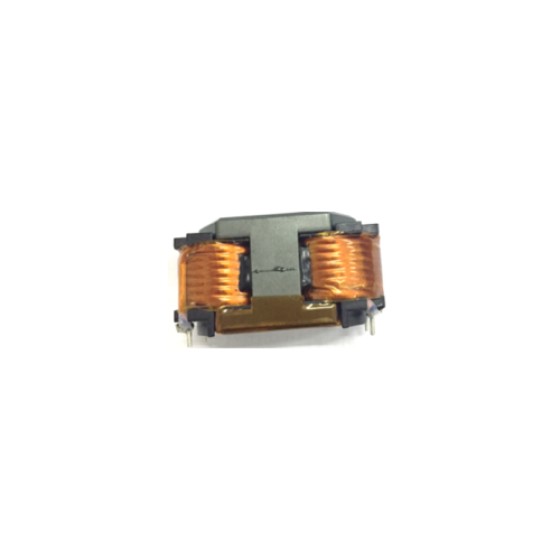
How Are Transformer Windings Insulated?
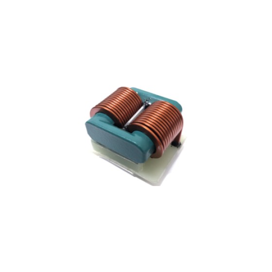
Transformer windings are one of the most important parts of a transformer. They carry electrical current and create the magnetic field needed for energy transfer. However, because the windings operate under electrical stress, proper insulation is essential to prevent short circuits, improve safety, and ensure long-term reliability.
Without a reliable insulation system, the transformer may suffer from winding failures, overheating, or electrical breakdown during operation.
Why Do Transformer Windings Need Insulation?
A transformer contains multiple windings that operate at different voltage levels. The primary winding is connected to the input source, while the secondary winding delivers power to the output circuit.
These windings must remain electrically separated while still being magnetically connected through the core.
Insulation serves several important functions:
- Prevents short circuits between adjacent wire turns
- Separates primary and secondary windings
- Protects against high voltage stress
- Improves transformer safety
- Increases operating lifespan
The insulation system is carefully designed according to the transformer voltage, frequency, temperature, and application requirements.
Enamel Insulation on Magnet Wire
The first layer of insulation is usually applied directly to the copper wire itself.
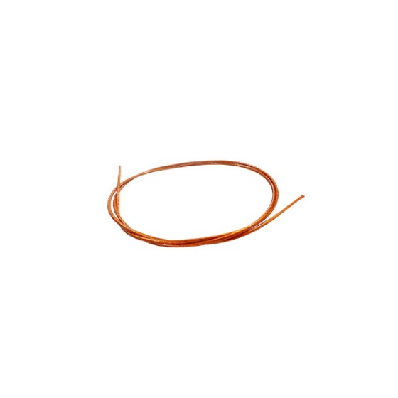
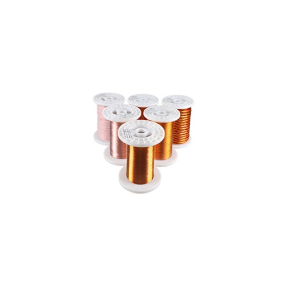
Transformer windings are commonly made using enamel-coated copper wire, also known as magnet wire. A thin layer of insulating enamel covers the copper conductor, allowing multiple turns of wire to be placed closely together without electrical contact.
The enamel coating must withstand:
- High temperature
- Mechanical stress during winding
- Electrical voltage between turns
Different grades of enamel insulation are selected depending on the operating environment and temperature requirements.
Insulation Between Winding Layers
When a transformer winding contains many turns, the voltage difference between layers can become significant. Additional insulation materials are used between winding layers to improve protection.
Common layer insulation materials include:
- Polyester film
- Polyimide film
- Insulation paper
- Adhesive tape
These materials help prevent breakdown between different sections of the winding and improve mechanical stability.
Primary and Secondary Winding Isolation
In many transformers, especially power supply transformers, the primary and secondary windings require strong electrical isolation.
The insulation between these windings is designed to meet safety requirements and prevent dangerous voltage transfer from the input side to the output side.
Manufacturers may use:
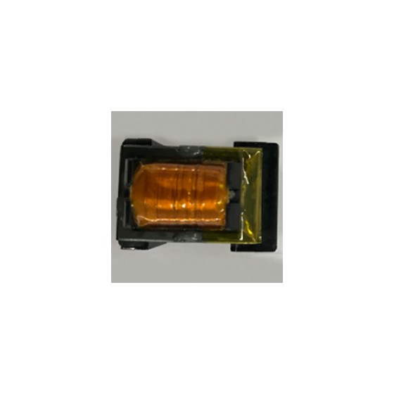
- Multiple layers of insulation tape
- Insulation barriers
- Safety margins in winding distance
- Triple insulated wire
This type of isolation is especially important in applications such as medical equipment, consumer chargers, and industrial power supplies.
The Role of Bobbins and Insulation Barriers
The transformer bobbin, also called a coil former, provides mechanical support for the windings and helps maintain proper insulation distances.
The bobbin design controls:
- Winding position
- Creepage distance
- Clearance distance
- Mechanical protection
Some transformer designs include additional insulation walls or barriers inside the bobbin to separate high-voltage and low-voltage areas.
Triple Insulated Wire
For compact high-frequency transformers, space is often limited. Triple insulated wire is sometimes used to simplify the insulation structure.
Unlike standard enamel wire, triple insulated wire includes multiple layers of protective insulation around the conductor. It can provide enhanced safety between primary and secondary circuits while allowing a more compact transformer design.
This type of wire is commonly used in:
- Flyback transformers
- AC adapters
- Battery chargers
- Compact switching power supplies
Insulation Materials and Temperature Rating
Transformer insulation materials must withstand the heat generated during operation.
Every insulation system has a temperature rating that defines its maximum continuous operating temperature.
Higher-temperature materials can improve reliability in demanding applications such as:
- Electric vehicle systems
- Industrial equipment
- Renewable energy products
- Data center power supplies
Selecting the right insulation material helps prevent premature aging and maintains electrical performance.
How Manufacturers Test Transformer Insulation
Before transformers are shipped, manufacturers perform insulation tests to verify safety and reliability.
Common tests include:
Hi-Pot Testing
A high voltage is applied between isolated parts of the transformer to confirm that the insulation can withstand electrical stress.
Insulation Resistance Testing
This measures how effectively the insulation prevents current leakage.
Creepage and Clearance Inspection
Manufacturers check whether the physical distances between conductive parts meet safety requirements.
These tests help identify potential insulation problems before the transformer is installed in a final product.
Insulation Challenges in High Frequency Transformers
High-frequency transformers, especially those using ferrite cores, face additional insulation challenges.
Higher switching frequencies can increase:
- Voltage stress
- Electromagnetic interference
- Parasitic capacitance effects
Therefore, transformer designers must carefully balance insulation performance with size, efficiency, and thermal requirements.
Final Thoughts
Transformer winding insulation is a carefully engineered system that combines wire coatings, insulating materials, structural design, and testing methods. It protects the transformer from electrical failures while allowing efficient energy transfer between circuits.
As electronic transformers continue to become smaller and operate at higher power densities, advanced insulation technologies will remain essential for improving safety, reliability, and overall performance.