



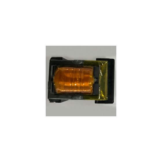

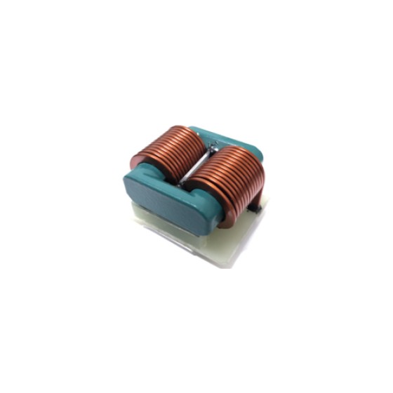
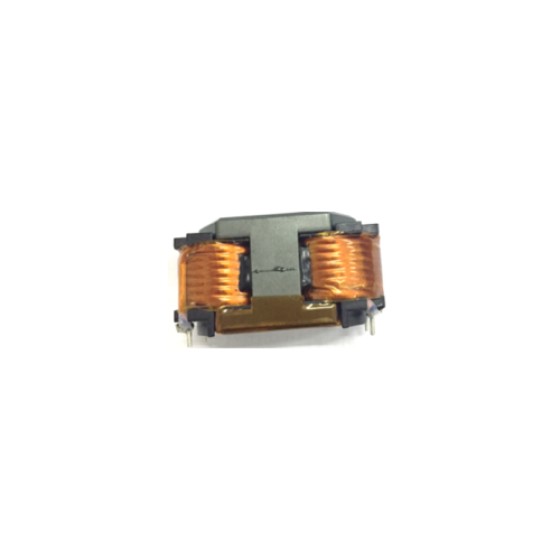
High Frequency Transformers Explained: Everything Engineers Need to Know
High frequency transformers are essential components in modern power electronics. Unlike conventional low-frequency transformers that operate at 50 Hz or 60 Hz, high frequency transformers are designed to work at switching frequencies ranging from several kilohertz (kHz) to several megahertz (MHz). Their compact size, high efficiency, and excellent power density make them the preferred choice for switching power supplies, renewable energy systems, industrial automation, electric vehicles, telecommunications, and consumer electronics.
What Is a High Frequency Transformer?
A high frequency transformer is an electromagnetic device that transfers electrical energy between two or more circuits through magnetic induction while operating at high switching frequencies. It provides voltage conversion, electrical isolation, and impedance matching in power conversion systems.
Compared with traditional transformers, high frequency transformers use ferrite cores instead of laminated silicon steel cores. Ferrite materials offer significantly lower core losses at high frequencies, allowing the transformer to operate efficiently while maintaining a much smaller size and lighter weight.
How Does a High Frequency Transformer Work?
A high frequency transformer operates based on the principle of electromagnetic induction. When a high-frequency alternating current flows through the primary winding, it generates an alternating magnetic flux inside the magnetic core. This changing magnetic field induces a voltage in the secondary winding, transferring electrical energy from the input to the output without direct electrical contact.
The switching frequency is typically generated by power semiconductor devices such as MOSFETs or IGBTs within a switching power supply (SMPS). Higher operating frequencies reduce the required core size and the number of winding turns, resulting in more compact transformer designs and improved power density.
Main Components
A typical high frequency transformer consists of several key components:
Ferrite magnetic core
Primary winding
Secondary winding
Insulation system
Bobbin or coil former
Shielding (optional)
Encapsulation materials (optional)
Each component plays an important role in determining efficiency, thermal performance, electrical isolation, and long-term reliability.
Advantages of High Frequency Transformers
High frequency transformers offer numerous advantages over conventional transformers:
Compact size and lightweight construction
Higher power density
Improved conversion efficiency
Lower copper and core losses
Excellent electrical isolation
Faster energy transfer
Reduced electromagnetic interference through optimized designs
Suitable for automated manufacturing
These advantages make them ideal for modern electronic equipment where space, efficiency, and performance are critical.
Common Core Materials
Selecting the appropriate magnetic core material is one of the most important design considerations.
Common materials include:
MnZn Ferrite
NiZn Ferrite
Nanocrystalline Core
Amorphous Core
Powder Iron Core (for specific applications)
Among these materials, MnZn ferrite is the most widely used for high frequency power transformers because of its excellent magnetic properties and low power loss.
Typical Applications
High frequency transformers are widely used in numerous industries, including:
Switching Power Supplies (SMPS)
AC/DC and DC/DC Converters
Battery Chargers
Solar Inverters
Electric Vehicle Charging Systems
Industrial Automation Equipment
Medical Electronics
LED Power Supplies
Telecommunications Equipment
Data Centers and AI Servers
Consumer Electronics
Smart Home Devices
As power electronics continue to evolve, demand for high frequency transformers continues to increase across both industrial and commercial markets.
Design Considerations
Engineers must consider several factors when designing a high frequency transformer:
Operating frequency
Input and output voltage
Output power
Core material selection
Core geometry
Winding arrangement
Insulation requirements
Thermal management
Efficiency targets
Safety standards
Electromagnetic compatibility (EMC)
Optimizing these parameters helps achieve maximum efficiency while minimizing temperature rise, leakage inductance, and electromagnetic interference.
Manufacturing Process
The manufacturing process generally includes:
Magnetic core selection
Bobbin preparation
Precision winding
Interlayer insulation
Lead termination
Assembly
Vacuum impregnation (if required)
Electrical testing
Hi-Pot and insulation testing
Final inspection and packaging
Modern transformer manufacturers increasingly employ automated winding machines, automated soldering systems, laser marking, and automated testing equipment to improve consistency, productivity, and product quality.
Future Industry Trends
The rapid growth of renewable energy, electric vehicles, AI computing, and industrial automation is driving demand for smaller, more effici